 |
 |
VK5ZVS |
|
| Projects 'n' Stuff |
|
 |
| Home | Back |
|
| |
| LC Meter. |
This project will prove to be a worthwhile addition to my equipment
and was fun to build. What can I say? I love electronics. What I'm finding interesting
at the moment is the number of projects using PIC chips that give results approaching lab
quality performance at much less than lab quality prices. This is an interesting time in electronics
for the hobbyist.
I've also implemented some improvements - using a low drop-out 5v regulator and
winding a custom inductor for the reference circuit, to improve stability and measurement error.
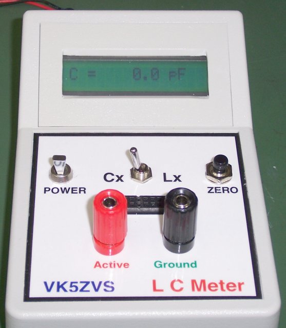
Calibration is performed first. Turnon the unit with the switch
in the Cx position with no components connected. Press Zero button briefly and the unit should now
read 0.0pF. Calibration done.
|
|
|
| |
|
|
| |
|
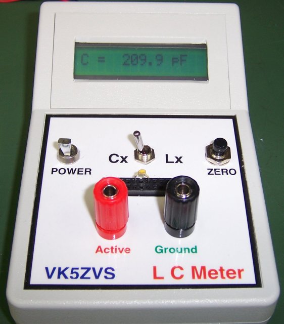
| Here's a photo showing a 220pF capacitor being measured
using a modified IDC connector, allowing a component to be inserted & measured quickly and easily.
It also acts as a mini-prototype board, so several components can be added together and measured
at the same time to get, say, a desired value. i.e. two capacitors connected in parallel to make
a required value of capacitance. Thanks to Paul, VK5AB, for the suggestion, the pcb and the single
line display.
|
|
|
| |
|
|
| |
|
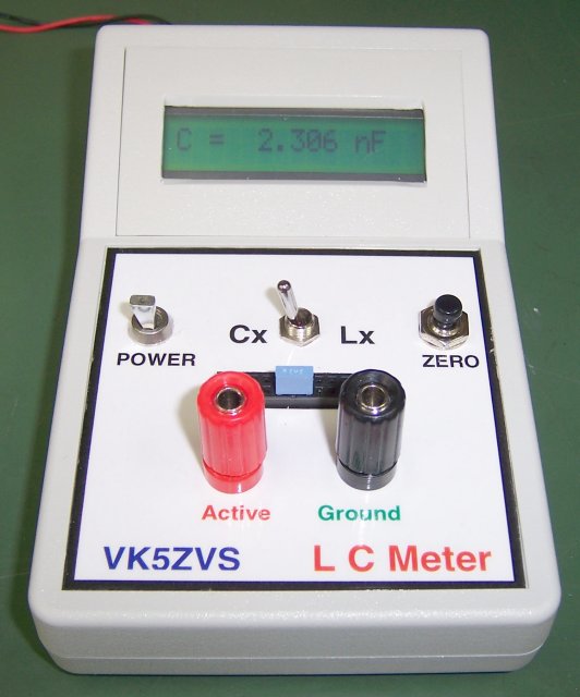
| Here's a photo showing a 2.2nF capacitor being measured.
What you thought was a 2.2nF capacitor, here you can see what it actually measures.
|
|
|
| |
|
|
| |
|
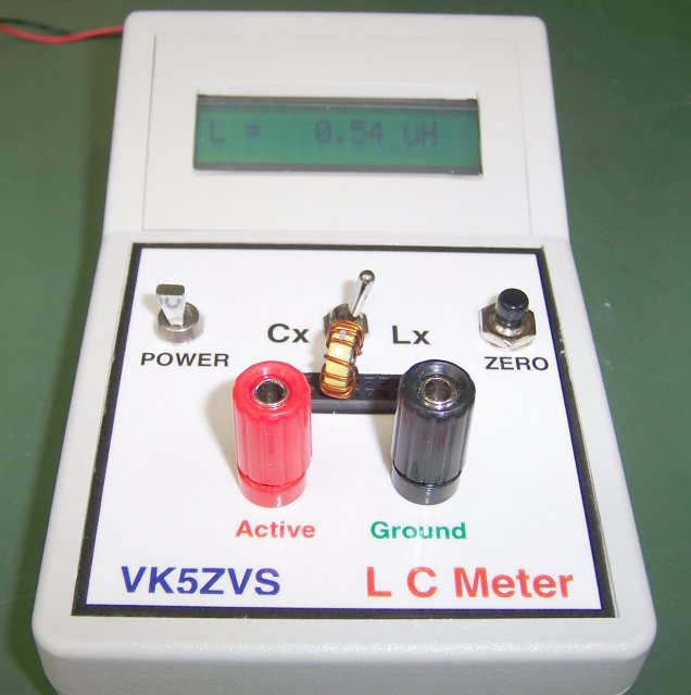
| Here's a photo showing a 0.54uH (540nH) inductor being measured.
Calibration is performed first, with the switch in the Lx position
and a short installed on either set of connectors and the zero button has then been pressed.
Remove the short and you're ready to measure.
|
|
|
| |
|
|
| |
|
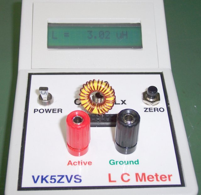
| Here's another photo, showing a 3uH inductor being measured.
|
|
|
| |
|
|
| |
|
|
|
| |
|
| Here's where the original schematic and code can be downloaded:
|
| Original article by VK3BHR includes parts listing and construction details.
Digital LC Meter Version 2
|
|
|
| |
|
|
|

